PMI Auto Generator
a machinist's best friend
Script automating CAD annotation, improving machinist efficiency by 30%.
View GitHub
Background
Manually transferring info from a technical drawing to a 3D CAD model can be tedious and the worst part of a machinist's day. Keep scrolling to find out how I cut production time by 30 percent!
What tools?
I used for the logic and for easy interfacing with applications. I also utilized MBDVidia's OCR for data extraction and file conversion.
Python
AutoHotKey
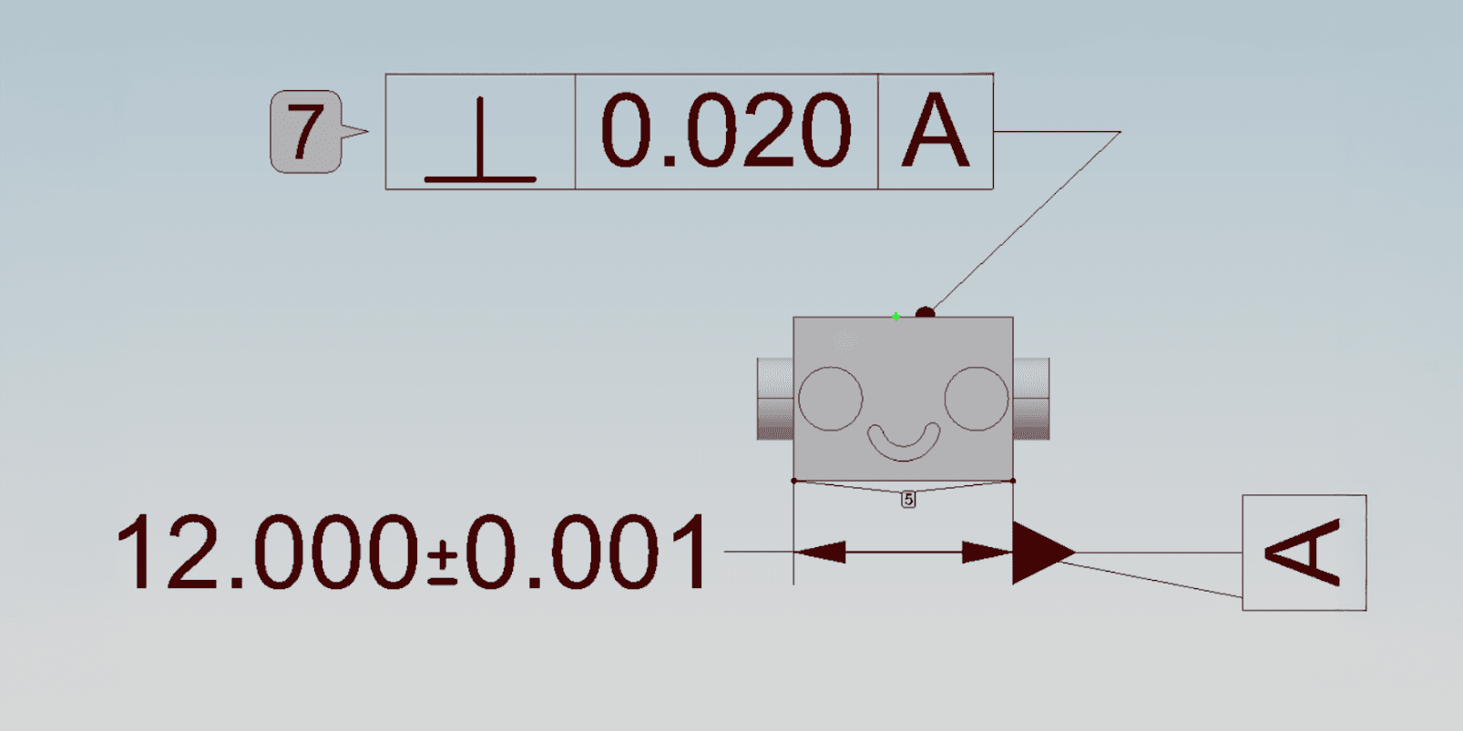
Pictured: Example 3D model with attached PMI
Why this project?
Working with CNC machinists at Autonomous Machining opened my eyes to the many unexpected challenges that come with producing machined parts, especially precision parts for aerospace and automotive systems.
At first, I thought the buyer companies just sent a SOLIDWORKS model, the machinist hit a few buttons, and the machine would cut it out—simple, like a 3D printer. However, I quickly learned that this isn't the case, and there are very good reasons to why machinists get paid in this economy.
As a machinist, it makes life a lot easier to have a 3D model that includes Product and Manufacturing Information (PMI), such as desired dimensions, tolerances, and specifications. This allows you to create machine paths and quality assurance procedures to the specs of the buyer.
But due to old-fashioned "this is the way it's always been done" practices, many times the machine shop only receives a stripped-down (no PMI) 3D model and a 2D PDF containing the necessary specifications. Someone then must manually annotate the model, which is a tedious and time-consuming task, especially for a small team like the one I worked with at my internship. Seeing this, I realized it had to change, and that was the birth of my PMI Auto Generator.
Pictured: Project demo video!
What is it?
Building on a blank 3D model and a PDF containing the necessary specifications, this is a Python application built to automatically attach all diameter annotations directly onto the 3D model. To format the files as needed, I created an AutoHotKey script to run on MBDVidia, the MBD software we used in the shop to attach the annotations. With a generated UI, the program guides the user to extract the annotations from the PDF into an Excel sheet, and convert the 3D model .stl or .sldprt file to a .qif file.
The .qif file is the key that my program relies on, as its XML structure allows me to parse and insert information without a GUI. This unlocks automation and greater speed capabilities, which I take advantage of through this project. Now, using Python with NumPy and openpyxl, it scrapes the Excel file and formats each entry to scan for diameter annotations. I've picked diameter annotations because the shop mostly worked with turned (cylindrical) parts, so diameter annotations made up about one-third of all dimensions.
The program then gets all of the dimensions from the model .qif file and cross-references each with the desired diameter dimensions. Lastly, it inserts those annotations onto the model. Then the user can simply open the .qif file and attach the rest of the annotations manually with the help of my MBD Macro. This project single-handedly saves around 30% of the total annotation time, and the full process takes only about 60 seconds to complete.
What did I learn?
I strengthened my Python and scripting skills, as well as my understanding of best practices for writing scalable and intuitive code such that non-experts could understand and use it effectively. This included creating Standard Operating Procedures (SOP) documentation and oral presentations to the team.
Some challenges that I faced included extracting data from non-standard part drawing PDFs, as well as completely reverse-engineering the QIF format with few available resources. This project also attracted the attention of the company's CEO, who invited me to present my work to the parent company's leadership team, and I received a light round of applause as I concluded.